Saturday 24 January 2015

V-Strom Hand-guard LED Lighting

This was something I did back in 2010 to increase the night-time visibility of the strom.
Firstly I had purchased an additional set of hand-guards to fix the winter guards to (see my other post for this) so I decided to use this pair to also install the lighting in to, leaving a stock set of hand-guards should I ever need them.


First was to buy some white LED waterproof strips from eBay
Mark the holes required on the hand-guard

Fit the strip from the inside

This allows the surface of the rubber housing to be pretty much flush with the plastic


Secure in place with silicone

The finished install.  Looks good imo

The effect is very 'Multistrada' esque

I powered them by tapping in to the parking lights on the strom 
They are even effective during daylight hours 
At dusk

At night

I like the way they add width to the bike, and studies show that this is seen much clearer by other road users at night

Cross threaded final drive shaft! ...and the fix

This actually occurred during my pre riding season spring maintenance back in May 2011, but although it was well documented on the VSRI forum, I thought it was time to add to my Vstrom blog. 
So here is the extracts from the original VSRI topic www.vstrom.info

I recently needed to change the chain kit on my DL650. What should have been a routine task turned into a big problem.  The retaining nut for the front sprocket was proving difficult to remove. It took a substantial amount of force using a breaker bar to release the nut. The resulting damage to the threads on the output shaft was not good.  The thought of how the damage occurred was either when the bike shop changed the last sprocket, they crossed threaded the nut with an airgun, or that whilst I was undoing it, the nut tangs broke or maybe there was too much gunk on the threads?  We'll never know.


The nut was finally removed revealing the horror of the stripped threads

The stripped nut
There was much discussiuon on the foirum as to what to do.  I did phone my local Suzuki dealer who said it would cost a mimimum of £1500 to strip the engine all the way down to get to the shaft which sits at the very bottom.  Therefore, I decided it was going to be a good home fix.  

The idea was to use a split die, view this video for an explanation YouTube.  However, a standard die off the shelf wouldn't work as I wanted to cut the thread in reverse, by starting it on the good thread that was left neaerest the engine, and turn it anti-clockwise out, cutting a new thread as it went.  So I spoke to a local tool maker  who we use at work.  He knows his stuff, and is a keen biker too.  Recently he restored a Bantam and a 1952 Bonnie T100.  


My drawing shows the amount of 'good' thread remaining on the shaft
The plan is to buy the standard M20x1.5p Die Nut, and he will use a wire-eroder to slice it in half and utilise a grub screw or something to hold it back together.  Below is the M20 split die that he made for me.  You can clearly see that my toolmaker has sliced it in half using the wire erroder.  The shims are to replace the width of the cut.
You can also see that I got him to machine a recess at one end.  This is so that it will fit over the splined shaft and make sure that all the cutting edges of the die start on the good threads.
The die has been reversed too, as we are cutting counter-clockwise.


The reversed thread split die
I bought a 38mm socket to turn the die.  My toolmaker machined some grub screws to ensure that the two half's of the die are pressed together when inside the socket.


38mm Socket with machined grub screw points to hold the die together
It was impossible to show in a picture, but this is the socket with the die inside.  And I am just nipping up the grub screws.  It was in fact extremely tricky to get the die & shims in the socket.
Its one of those things that seems simple when you go over it in your head - a different beast altogether in reality!  Perseverance and patience was the key here.


The assembled socket containing the split die
It was extremely nerve-racking when cutting the thread.  I would cut a bit, stop and dismantle the whole socket and check and make sure I wasn't damaging the good thread.  
I did this so many times, and to be honest I was cacking it!  I knew that if I fooked this up, it was strip-down engine time.
I used lots of lube, and finally the die was through.  This is the finished thread.  Now it might not look that great, but I am very happy with the result.


The new thread
The very badly damaged threads were never going to return, there just wasn't enough metal left to cut on to.  But it did ensure the good threads were cleaned up and that the thread would
start nicely and a nut would go on without cross-threading.  Here I had purchased an M20 std hex full nut to try out first before using the locking nut which comes with locking compund already.

Testing the new thread with a standard nut
And so the finished thing.  I have torqued the nut to 113Nm and put a marker as suggested by Greywolf/Preload. After a few rides and miles, I'll check it a few times.
But with the amount of good thread (ended up with about 1 thread protruding the nut), the lock nut, locking compund, good torque and a washer, I'd be surprised if this sucker moves!


Finished.  The new sprocket fitted

Thanks to everyone who offered suggestions.  They were all very warmly welcomed.


Friday 25 May 2012

Aux Lights Install

The main headlights on the Vstrom are brilliant, especially after changing the standard bulbs to Osram Night Breaker's which produce a much brighter and whiter beam.  However, the main problem with bikes is that the flasher can rarely been seen, especially in daylight hours.  Therefore I wanted to install some additional lights to come on when I flash my main beam.


The lights are a set of cheap LEDs in a waterproof housing


The brackets are a set of universal M10 mirror mounts (ebay link)
The Allen bolts are M10x1.25p cut down to about 12mm


Making a wiring loom for your lights prior to install makes life a lot easier  


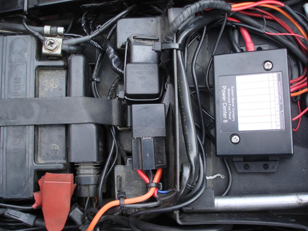
This harness is wired complete with a relay using power from the aux fuse box rather than drawing more power from the lighting circuit


This shows the harness and relay in situ on the bike, wired 
in to the Aux fuse box  


The harness wire that has the diode is spliced in to the 
head light flasher circuit.
Here is the main fuse box removed and turned upside down.


The yellow cable is the flasher circuit and the orange 
cable is from the new harness.
There are several ways to do this, but as there is almost no slack 
in the bike cabling,
I decided to bare the yellow wire and solder directly to it.


Twist the wires together, and let solder flow in to the join


I finished off with wrapping the join in self-amalgamating tape

I already have an auxiliary shelf installed, so this is where
I have mounted the switch 
This waterproof switch is push on/push off type (ebay link)

 The switch allows me to have them permanently on, or off and just
come on with the high beam flasher

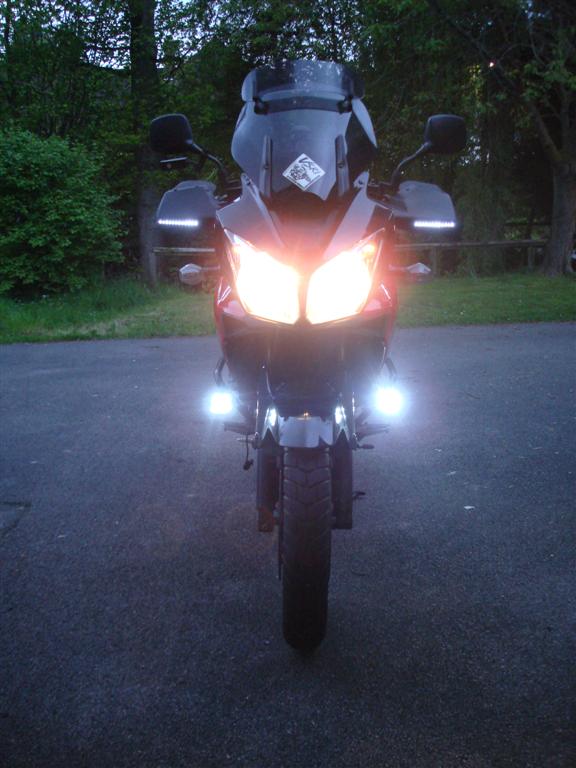
Here is the finished install


The 22mm Mirror brackets are a perfect fit on the SW Motech engine bars


The wiring is cable-tied along the lower bar


This mounting arrangement provides three separate joints and provides some 
nice flexibility to line up the lights exactly where you want them


Daytime image

Dusk image

Evening image


Sunday 1 May 2011

Stripped Engine Shaft!

During a run-of-the-mill tech day earlier this year, it was time to do the chain and sprocket change.  Unfortunately it proved to be nothing like a run-of-the-mill days.   


We had terrible trouble trying to remove the front sprocket retaining nut.  At one point, my strapping fellow biking buddies Steve and Dino were standing on the breaker bar to try and turn the nut.  Eventually after much sweat and an almost toppled bike, the nut finally came off, and with it left behind a complete nightmare.  The nut and output shaft threads were completely
chewed to pieces!!!  


We reckon that the shop who replaced it last time, managed to cross thread the nut and forced it on with an air gun.  A call to my local Suzuki dealer confirmed in the 'likely' event that the thread is not salvageable, this would mean a complete engine re-build to replace the shaft that runs right through the gearbox.  This would cost over £1000 for labour alone, more like £1500 with parts.  So not being happy with that news, I set about a repair.  


Here's what happened..


With the nut finally off and a clean of the shaft clearly reveals the nightmare stripped shaft


You can see that there is good thread on the inner part of the shaft. Hmm.. 


Here is my rough drawing and measurements of what I have to play with.
I have caluated that if I can get a new nut on, there is
sufficient thread remaining to hold it
So the idea was to use a Hex Die and split in in two halfs


This is the M20 split die that I bought.  You can clearly see that my toolmaker has sliced it in half using the wire erroder.  The shims are to replace the width of the cut.
You can also see that I got him to machine a recess at one end.  This is so that it will fit over the splined shaft and make sure that all the cutting edges of the die start on the good threads.
The die has been reversed too, as we are cutting counter-clockwise.


This is the 38mm socket to turn the die.  My toolmaker machined some grub screws to ensure that the two half's of the die are pressed together when inside the socket.


It was impossible to show in a picture, but this is the socket with the die inside.  And I am just nipping up the grub screws.  It was infact extremely tricky to get the die & shims in the socket.
Its one of those things that seems simple when you go over it in your head - a different beast altogether in reality!


It was extremely nerve-racking when cutting the thread.  I would cut a bit, stop and dismantle the whole socket and check and make sure I wasn't damaging the good thread.
I did this so many times, and to be honest I was cacking it!  I knew that if I fooked this up, it was strip-down engine time.
I used lots of lube, and finally the die was through.  This is the finished thread.  Now it might not look that great, but I am very happy with the result.

The very badly damaged threads were never going to return, there just wasn't enough metal left to cut on to.  But it did ensure the good threads were cleaned up and that the thread would
start nicely and a nut would go on without cross-threading.  Here I had purchased an M20 std hex full nut to try out first before using the locking nut which comes with locking compund already.


And so the finished thing.  I have torqued the nut to 113Nm and put a marker as suggested by Greywolf/Preload. After a few rides and miles, I'll check it a few times.
But with the amount of good thread (ended up with about 1 thread protruding the nut), the lock nut, locking compund, good torque and a washer, I'd be surprised if this sucker moves!

Monday 14 March 2011

Lighting up a V-Strom

This small project was to add some extra lighting to the bike, and specifically to make the appearance quite wide at night time for on coming vehicles to see me better.
I had seen the new Ducati Multistrada and its very impressive LED's on the hand-guards, and the intention was to try and mimic this effect using much cheaper materials.


So lets see how it turned out?..


Strip of waterproof 12V white LED's encased in silicone
Time to mark and drill some holes in the handguard


They seem to fit nice and snug


Slightly protruding on the front face is intentional


Some silicone to fix in place


So far so good


Testing with a 9V battery


And fitting on the bike and run from the 12V supply


Very effective at night!